![]()
Lego Power Functions Hacking Guide – Part 4 – Wiring the Arduino
Part 1 – Introduction
Part 2 – Equipment
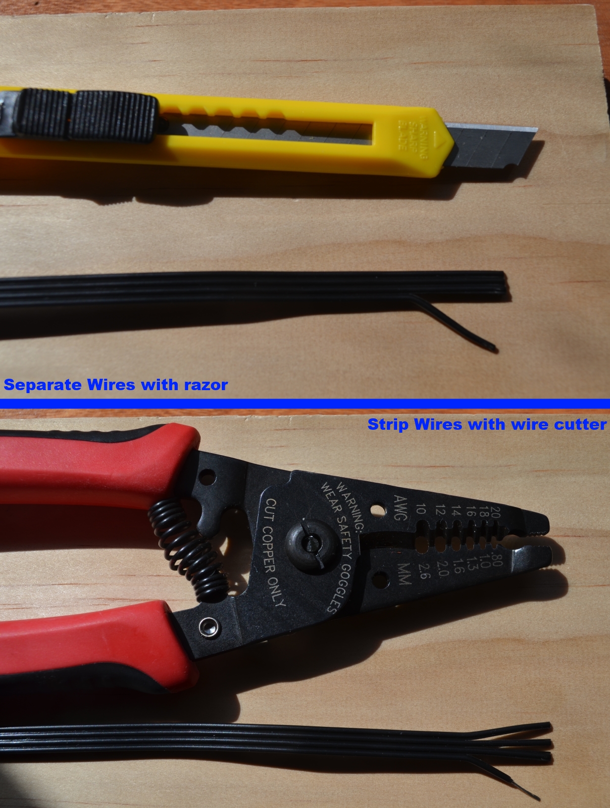
Part 3 – Wire Hacking
Part 4 – Wiring the Arduino
Part 5 – Programming (coming soon)
The saga continues! Bust out the breadboard because its time to make use of those Power Functions wires we just defiled with our wire cutters.
Breadboard Schematic

Breadboard layout for connecting our lego motor and Arduino to our motor driver
The above picture shows roughly what our breadboard will look like after we connect our Arduino and Lego parts to our DRV8833 motor driver. I included the reference schematic from Pololu in the upper right hand corner so you can see which pins we are connecting too. If you missed the link from the equipment post you can find the Pololu product page HERE
Layout Description and Explanation
I’ll provide a quick overview before I move on to a detailed list of our connections. The central focus of our circuit is the DRV8833 motor driver in the middle of the breadboard. It is what converts our low power signals from the Arduino to the high power outputs that a motor needs to run. Two lines are used from the Arduino to drive the motor (essentially one for each direction) and the Lego motor is tied to the corresponding motor output. The Arduino power is used for the logic side of the driver and the lego battery box is used to power the motor side.
Detailed Connection List:
1) Arduino Power
The 5V and Gnd from the Arduino are wired to the upper power rails of the bread board. This power rail is now the “Logic Power” for our circuit. Logic ground is tied in to the motor driver ground pin. (When two separate power supplies are used, as is often the case with motor applications, the grounds of the power supplies need to be tied together for them to interact. The motor driver does this for us)
2) Arduino Control Signals
To drive a motor you need two control signals. Each control signal ties to one of the motor wires (C1 and C2 in our case). For our control signal connections we need Arduino pins that are capable of PWM output so we can control motor speed. For this circuit I chose pins 6 and 9, both are PWM enabled. These lines will tie in to our AIN1 and AIN2 pins on the motor driver. (The motor driver can control two motors, we’re only using one so we will use the ‘A’ pins)
3) Motor Power
Motors require a higher amount of power than control circuits can handle so its good to use a separate motor power supply to drive them. In our case we are going to use the standard lego battery box and one of our hacked Power Functions wires we made in the previous PF Hacking post. Attach the Lego block end to the battery box. The hacked end we will connect to the breadboards lower power rail. Tie the 9V line to the red rail and the Gnd line to the black rail. The C1 and C2 wires are not used and can be taped off with electrical tape. BE CAREFUL THAT C1 and C2 DO NOT TOUCH. They will short out if power is turned on and they are touching. This is why either electrical tape or simply cutting them off is important. (PHOTO COMING SOON)
4) Lego Motor
Time to use that last hacked wire. Attach the lego block end of the wire to the lego block connector of your motor. At the other end, attach wire C1 to AOUT1 on the driver and wire C2 to AOUT2. Use electrical tape on the unwired 9V and Gnd lines from our hacked cable.
(PHOTO COMING SOON)
5) Capacitors (optional)
With motor applications its always helpful to add capacitors to the the power rails to help protect against spikes and dips that can occur when a motor is first started. Standard 10uF capacitors work great. These are optional but helpful and recommended.
Putting it all together
When you are done you should have something that looks a lot like the picture below. Once that is done its time to move on to the final steps of programming our Arduino! Stay tuned for the final post in the Lego Power Functions Hacking series where we get it all running and moving!
(Photo and Video of final circuit coming soon)