So I’m realizing that I’m way to stuck on long form posts and need to get in to the habbit of just posting anytime I have an update. Otherwise I get caught up in being to busy and just don’t post at all… for months lol. So here goes short form!
I’ve always wanted to have a web based interfaced for many of my projects and lately I’ve finally come around to teaching myself web programming. My platform of choice is the Beaglebone Black. I’m writing the server side in Python with a module called Flask that acts as a web host for the web page portion. On the web front I’ve been learning all the necessary components for that. Namely HTML, CSS, and JavaScript. That’s four languages to learn all in one go! Its a lot but the web languages especially are so ubiquitous that its not bad to pick up. When its all said and done I should good code base for future projects that I can use to create web interfaces! Then just about every device with a web browser suddenly becomes a remote control.
I’m building towards making a nice looking web interface for my laminar fountains but my learning project is to build a simple controller for a Model Railroad. Eventually it will consist of a single motor controller for power and a few relays/triacs for switch control. My father recently pulled his N scale model train layout out from storage after nearly two decades and I thought it would be fun to build him a controls upgrade.
Water water everywhere! There are no two ways about it, water fountains are just plain fun. Show a water fountain to any five year old and just see if they don’t start playing and giggling. Which leads me to this conclusion: I never grew up because I still get a ridiculous grin on my face when I get to play in a water fountain. And the coolest of all the fountains in my opinion is the laminar fountain. I built a laminar fountain a few years back and am now working on designs for a 3D Printed laminar fountain which I will post online once I get a semi-working alpha version. In preparation for all that let me explain a little about what laminar flow and fountains are.
What is laminar flow? The simplest way to explain laminar is probably to say that it is the opposite of turbulent flow. Turbulent flow is the most common type of flow you will see in nature. A drinking fountain is a good example of turbulent flow with how blobby and wiggly the water is when it comes out. White water rapids in a river would be an extreme case of turbulent flow. So in contrast, laminar flow is super smooth flowing liquid or gas. The full reality of laminar flow is that it means all of the water particles are flowing exactly parallel to each other, in the same direction, and as such are not bumping in to one another.
Laminar flow profile showing the velocity of water as it moves through a pipe. (Taken from wikipedia)
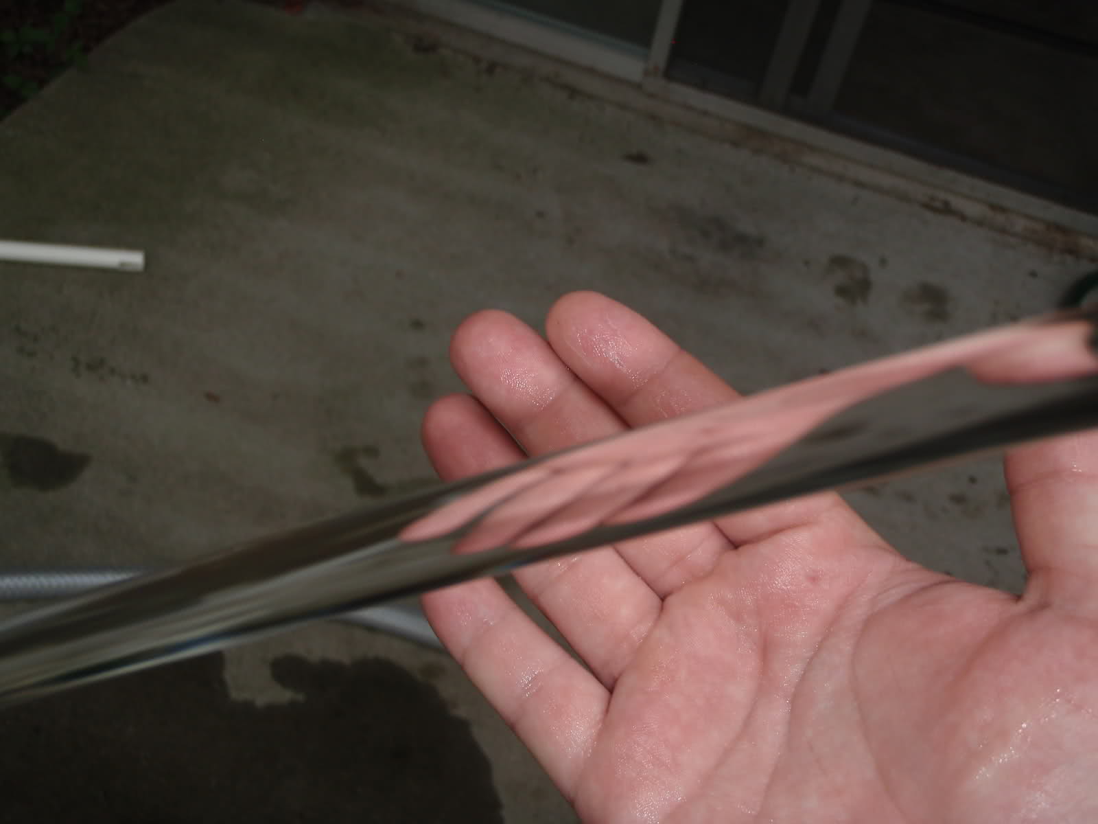
Real world picture of a laminar water stream after it exits my laminar fountain. Because the water is all flowing in the same direction it stays perfectly together and creates a glass rod effect where light can pass right through.
So why it cool? Because it’s science! But also because it has some really cool application properties we can make use of:
1) Its moving… buts it doesn’t look like it
Because a laminar stream is perfectly smooth the flow path will stay in exactly the same place at all times. A traditional fountain will wobble and sputter as it pumps water out which makes it very obvious that the water is moving since you can follow the individual water blobs as they pass through the air. A laminar stream is perfectly uniform and does not waver which means there are now individual water droplets to follow with your eyes. The water is flowing quickly but its hard to tell. It literally looks like a perfect glass arch coming from the fountain going all the way to where it hits lands. (See the picture above)
2) No splash
Because the water stream is so smooth it will not break apart when it encounters another body of water or smooth object. If it lands in a pool of water it will disappear without a trace. If you put a smooth ball in its way it will spread out and wrap around the ball without splashing. Its a really cool effect and also has the benefit of making it quiet too!
3) It Jumps
Because the flow stream is so smooth it has a nifty visual effect when you suddenly block the stream. It looks like the stream is “jumping”. The water that is not blocked continues to fly through the air on the original path and stays together. You get little water snakes that that fly through the air. If you string multiple fountains together you can create the illusion that water is jumping from one fountain to the next.
4) It transmits light like a fiber optic cable
A fiber optic cable is a perfectly smooth medium that transmits light from one end to the other. The perfectly smooth sides of the cable reflect the light inside back in to the cable to keep it bouncing down the length until it reaches the other end. A laminar stream also has super smooth sides and therefore will also bounce light back inside of itself. This means that if you shine a bright enough light directly in to the laminar stream it will light up all the way from end to end! Even around the curve!
Here is a cool video that shows the laminar fountain forum user MagicNozzle posted of his home made fountain that demonstrates several of these properties (feel free to skip ahead, the night shots at the end are especially cool). Original forum post HERE
Laminar Maths: If you’re in to math and the equations that govern when a stream is laminar than this is the section for you. I find it super cool how this works so lets dig in!
In an engineering fluid dynamics class (study of moving liquids, a really fun course) you learn about the Reynolds number which will tell you if a fluid’s flow is laminar, transitional, or turbulent. Here is the equation from Wikipedia:
AHHHHHH!!!1!1!! Maths! *Deep Breath* This equation is actually super simple so hold on and keep reading.
Hold on, we’ll kick that scary equation in the teeth. Lets start by focusing on the first variation of the equation listed.
Re = (p*v*D)/u
Two of those are actually constants. p is the density of water which we can google (1000Kg / m^3) and u is the dynamic viscosity of our fluid (water is 0.000404 at room temperature). So putting those back in and simplifying we get this:
Re = (2.475×10^6)*v*D
That’s not so bad. v is the velocity of our fluid in the pipe in meters per second and D is the internal diameter of our pipe in meters which should be pretty easy to calculate. Once we have our Reynold’s Number (Re) we can see if the flow will be laminar. An Re value below 2300 means that the flow is Laminar. An Re value between 2300 and 4000 is Transitional and an Re value above 4000 is Turbulent. All this means that we need to adjust our water velocity and pipe diameter to get an Re below 2300 for our fountain. That’s all the math!
How the math works in real life:
So now that we have the math (or trust me if you didn’t read it) we can interpret it. This is what it all boils down to in real life:
The faster the velocity of the fluid and the bigger the pipe, the more turbulent the flow will be.
Or inversely:
The slower the fluid and the smaller the pipe the more laminar the flow will be.
So to put this in to the real world lets tackle one problem at a time and start with velocity. We need a certain minimum amount of volume flow to achieve the fountain size we want. For instance, the pump I used in the pictures above is rated at 500 gph (gallons per hour) which gave me the nice big water arch you see. The problem shows up now in that the velocity is found by dividing the flow rate by the cross sectional area of the pipe which is a function of pipe diameter as well! So we need a bigger diameter to slow the velocity down but a smaller diameter to get a low reynolds number…… Crap.
But what if I told you we could have a separate diameter to use for velocity and the diameter in the Reynold’s equation? The trick is to take a large pipe (8 inch PVC here) and pack it full of small pipes (drinking straws). This way you get to use the large diameter of the PVC for the velocity part and the small individual diameters of the drinking straws for the Reynold’s diameter. Bingo! We can now achieve laminar flow!
Inside my laminar fountain are nearly 2000 drinking straws to give a small diameter to the water flowing through while keep the slow velocity of a big 8 inch outer pipe.
Theory crafting complete! That’s it for the what a laminar fountain is. Stay tuned for some more posts talking about my first laminar fountain and how I am hoping to use my 3D Printer to start a new cycle of designs!
The saga continues! Bust out the breadboard because its time to make use of those Power Functions wires we just defiled with our wire cutters.
Breadboard Schematic
Breadboard layout for connecting our lego motor and Arduino to our motor driver
The above picture shows roughly what our breadboard will look like after we connect our Arduino and Lego parts to our DRV8833 motor driver. I included the reference schematic from Pololu in the upper right hand corner so you can see which pins we are connecting too. If you missed the link from the equipment post you can find the Pololu product page HERE
Layout Description and Explanation I’ll provide a quick overview before I move on to a detailed list of our connections. The central focus of our circuit is the DRV8833 motor driver in the middle of the breadboard. It is what converts our low power signals from the Arduino to the high power outputs that a motor needs to run. Two lines are used from the Arduino to drive the motor (essentially one for each direction) and the Lego motor is tied to the corresponding motor output. The Arduino power is used for the logic side of the driver and the lego battery box is used to power the motor side.
Detailed Connection List: 1) Arduino Power
The 5V and Gnd from the Arduino are wired to the upper power rails of the bread board. This power rail is now the “Logic Power” for our circuit. Logic ground is tied in to the motor driver ground pin. (When two separate power supplies are used, as is often the case with motor applications, the grounds of the power supplies need to be tied together for them to interact. The motor driver does this for us)
2) Arduino Control Signals
To drive a motor you need two control signals. Each control signal ties to one of the motor wires (C1 and C2 in our case). For our control signal connections we need Arduino pins that are capable of PWM output so we can control motor speed. For this circuit I chose pins 6 and 9, both are PWM enabled. These lines will tie in to our AIN1 and AIN2 pins on the motor driver. (The motor driver can control two motors, we’re only using one so we will use the ‘A’ pins)
3) Motor Power
Motors require a higher amount of power than control circuits can handle so its good to use a separate motor power supply to drive them. In our case we are going to use the standard lego battery box and one of our hacked Power Functions wires we made in the previous PF Hacking post. Attach the Lego block end to the battery box. The hacked end we will connect to the breadboards lower power rail. Tie the 9V line to the red rail and the Gnd line to the black rail. The C1 and C2 wires are not used and can be taped off with electrical tape. BE CAREFUL THAT C1 and C2 DO NOT TOUCH. They will short out if power is turned on and they are touching. This is why either electrical tape or simply cutting them off is important. (PHOTO COMING SOON)
4) Lego Motor
Time to use that last hacked wire. Attach the lego block end of the wire to the lego block connector of your motor. At the other end, attach wire C1 to AOUT1 on the driver and wire C2 to AOUT2. Use electrical tape on the unwired 9V and Gnd lines from our hacked cable.
(PHOTO COMING SOON)
5) Capacitors (optional)
With motor applications its always helpful to add capacitors to the the power rails to help protect against spikes and dips that can occur when a motor is first started. Standard 10uF capacitors work great. These are optional but helpful and recommended.
Putting it all together
When you are done you should have something that looks a lot like the picture below. Once that is done its time to move on to the final steps of programming our Arduino! Stay tuned for the final post in the Lego Power Functions Hacking series where we get it all running and moving!
The 3D Printer is up, running, and calibrated! My wife and I have been having a blast with it so far and its been running non-stop the last two weekends. Its been quite a learning experience figuring out how to calibrate it precisely. Delta style printers like the Mini Kossel are really robust and fast but due to the trigonometry required to converted x,y,z coordinates to tower movements the calibration can be a bit tricky. There is a fantastic blog post HERE that walks you through step by step how to calibrate your printer.
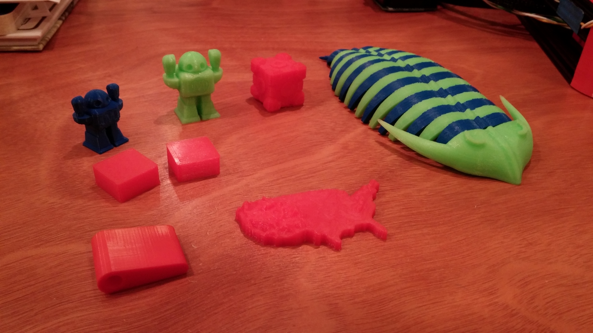
Now for a little show and tell. Here are a few of the things we’ve been able to print so far and a video showing the printer at work!
A few of the things we’ve printed
More to come as we keep printing and learning about building our own 3D Models!
ScuttleBot TFT Concept Design on my EasyPIC Fusion board
Recently I’ve been working on a 3D Printer Interface concept tentatively called ScuttleBot TFT. It started when I was looking for an interface for my upcoming Mini Kossel 3D printer build. I saw several multi-line character displays but not much in the way of color graphic or touch screen interfaces. So I struck out to make a color touch screen interface concept on my MikroE EasyPIC Fusion board to see what I could come up with and how much interest people would have for something like this.
The cool thing is that this can run on MikroE’s mikroMedia for PIC32 board which is compact and at $99 falls under the all important $100 price point (barely, but still makes it). It also includes a MicroSD card slot to read STL files from for computer free printing. It would be pretty easy to mount the board to a printed enclosure and attach it to the frame somewhere. The MikroMedia and my EasyPIC Fusion have the same hardware so the port from one to the other is super easy.
Front and back of the MikroMedia for PIC32 board
The concept code is done using MikroElektronika’s VisualTFT and MikroC Pro for PIC32. My initial concept is mostly interface design and screen navigation. I haven’t gotten very far in to the communications interface code with the firmware on my Ramps controller board yet but I have some ideas outlined on how to do it. One of my design goals is to make it user selectable from the touch screen whether to use SPI or I2C. Giving the option to use both would allow for maximum flexibility with other addons user might have.
The other part of this is figuring out exactly what should go on the screen. I am unfortunately still waiting on my last package for my printer that happens to contains the printed frame parts and motors (sitting in US customs, boo!) so I have yet to really experience the process of calibrating and using a 3D printer on a day to day basis. Without that its rather hard to know what should be on the screens, what should be most accessible, and what is mostly frivolous information that would just be in the way. Hopefully I’ll cure that soon but for now I’m trying to get a framework built to make it easier to move things around and communicate information to and from the print controller board.
We’ll see where it goes and how interested people. Even if I find there is already a cheaper color touch screen interface out there I didn’t come across in my initial search I figure the knowledge I gain by building this project will help me substantially in understanding the specifics of 3D printer control and firmware.
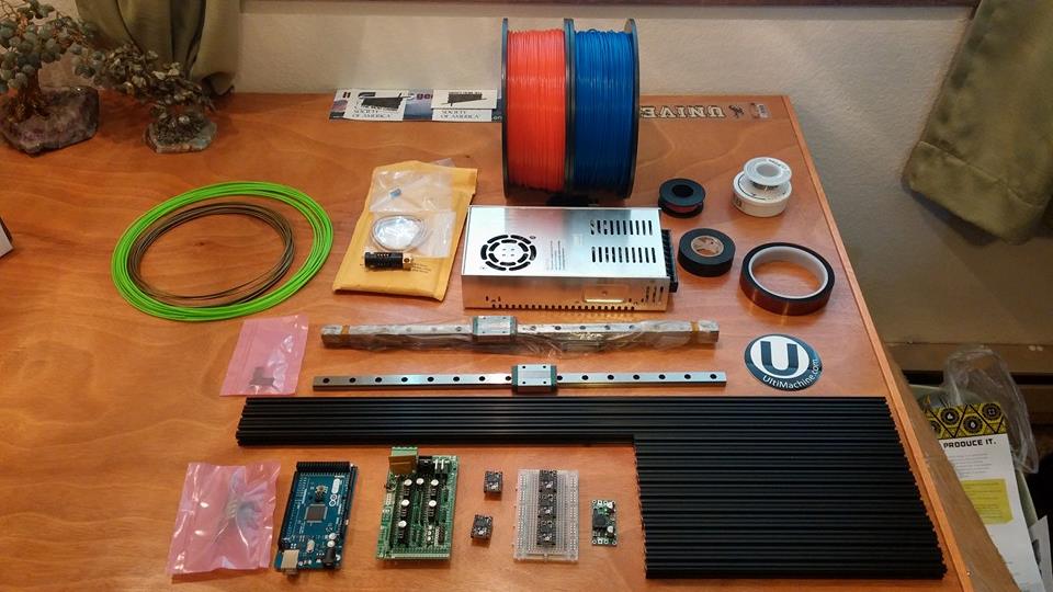
The first round of parts for our 3D printer is here!
My wife and I have decided to build a 3D Printer together for a fun couples project. That and who doesn’t want a 3D printer? I did a lot of research trying to find which printer we wanted. These were my criteria:
Had to be a kit or from scratch build
Had to be unique in some way (just for the cool showing off factor)
Had to be open source and easily modable/hackable
Preferably the base designs had to come from a reputable source
The design we settle on was the Openbeam Mini Kossel (Link)
The kossel is a part of the delta bot family of printers. Meaning that instead of moving the parts strictly in Cartesian coordinates the printer works by moving shuttles on three vertical drive towers to achieve the movement of the print head in the standard X, Y, Z planes. It makes for a solid design and also a very unique and fun looking build!
The Mini Kossel is an open source design originally created by Johan Rochel. Currently their aren’t any places that sell completed kits for the kossel so it has a very active and welcoming community of users who have created one with their own twists and methods. We decided to go with the standard mechanical build to start with that uses linear slide rails for the tower carriages. The modable part I want to start working on is a touch screen interface for running the printer computer free. I’m toying with VisualTFT software from MikroElektronika and a PIC32 MCU to drive the touchscreen and SD card reader. We’ll see where it goes!
Lego Power Functions Hacking Guide– Part 3 – Wire Hacking Part 1 – Introduction Part 2 – Equipment Part 3 – Wiring Hacking
Part 4 – Wiring Arduino (coming soon)
Its time to hack! Break out the wire cutters and soldering irons cause its about to get real.
Step 1 – Grab your LEGO PF extension cables
The first thing we will need to do is prepare our extension cables so that one end can be hooked up to our legos and the other can go in to a breadboard for attachment to Arduino and motor controller.
LEGO PF Extension Wires – Top wire is hacked, bottom is a normal wire before hacking
As you can see in the picture above the extension wires have two different colored heads on them, one light grey and one dark grey. We’re going to cut off the light grey end as close as possible to the plastic head to leave as much wire as we can. (Side note: the underside of the light grey end converts PF to old Mindstorms motors which is why we are cutting off that end). The goal is to achieve what you see with the top wire in the picture. A LEGO connector on one end and bare wires on the other.
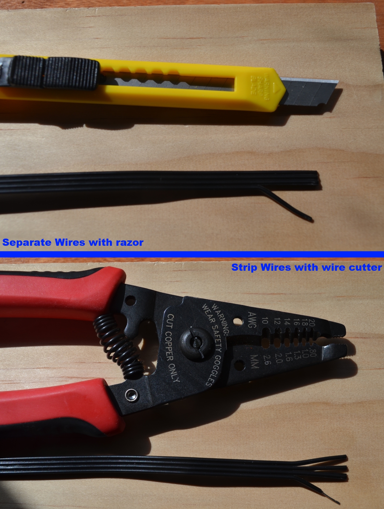
Step 2 – Cut and Strip the wires
As mentioned above, take your extension cable and cut light grey end off as close to the plastic as possible. You should come out with the four wires that make up the cable all stuck together by their insulation. Now we need to prep the wires for use with a bread board
Separate then strip each wire
The first thing is to separate each of the four wires from each other using a razor or utility knife to cut the areas between each wire’s insulation. The insulation is thin so you have to be careful to stay straight and not bite in to a wire. I find this easiest by laying the blade edge flush with the area to be cut and then pushing straight down to do the cut all at once.
Next you need to strip the separated wires of their insulation. I used a wire stripper that can do 22 gauge stranded wire (20 gauge solid). I highly recommend a wire stripper as seen in the picture as the wire is very small and stranded which makes it easy to cut off strands when doing it with a razor blade.
Step 3 – Tin the wiresand do it again for a second cable!
The final step is to tin the wire ends. This means to use a soldering iron to apply a small amount of solder to the end and bind the strands all together. This makes is much much easier to insert the wires in to a solder-less breadboard for use with the Arduino. You should end up with an end that looks something like the picture below. For help with Tinning do a search on youtube as there are many examples. We will need two of these cables so make sure you complete a wire in the exact same way.
Wires tinned and ready for use!
Step 4 – Know your wires!
Congratulations! You have two wires hacked and ready to go (hopefully). Now we need to learn a little something about what each of the four wires does. In the picture below I have labeled each of the four wires from the top view of the cable (Lego nubs facing up on the connector)
Power Functions cable showing the use of each wire
C1 – control wire 1 – 9V when battery pack is forward, 0V when in reverse
C2 – control wire 2 – 0V when battery pack is forward, 9V when in reverse
9V – power wire – On when battery pack is on (9V regardless of pack direction)
The two outside wires are our power and ground. Anytime a LEGO battery pack is connected and turned on these wires will be the same and do not change polarity. The two inside wires are the motor control wires that power the motors themselves. When a battery pack has its direction switch changed it reverses the polarity of these two. When C1 is high and C2 is low the motors rotates forwards. When C1 is low and C2 is high the motor rotates backwards. If you have a PF infrared speed controller in your system the speed controller applies a PWM signal to C1 or C2 to regulate the speed.
Step 5 – Our design
What we are going to do is use one of our cables to draw power from the LEGO battery pack via the outside two wires and then use our second cable with the inside two wires to attach the PF motor to our motor controller. Stay tuned for how to wire this up with the Arduino!
Lego Power Functions Hacking Guide– Part 2 – Equipment Part 1 – Introduction Part 2 – Equipment Part 3 – Wiring (Coming Soon)
Welcome to Part 1 of my Lego Power Functions hacking guide! For those who skipped the intro post I’m demonstrating how to hack Lego Power Functions (part of Lego Technic) for control with your own microcontroller. In this guide I will be using the Arduino Uno to control our Legos.
To get started I’m going to go over the things we will need as a part of this guide:
Equipment Shown: 1) Lego Power Functions Medium Motor 2) Lego Power Functions 9V Battery Box 3) Lego Power Functions Extension Cable (8″ or 20″) 4) Lego Technic Axel (optional) 5) Arduino Uno 6) Arduino CC3000 Wifi Shield (optional) 7) Breadboard jumper wires 8) Dual Motor Driver (DRV8833, can be others) 9) LED and 330 Ohm Resistor
1) Lego Power Function Motor
This is the standard Lego motor with four wire connection. It can be purchased as part of a kit (Link) or separately (Link). The Large and XL motor options also work.
2) Lego Power Functions 9V Battery Box
This is one of two Power Functions battery boxes. Both work just fine. This one comes in the Power Functions kit linked above with the motor or can also be had separately. (Link)
3) Lego PF Extension Cable
These cables are what we are going to hack to connect to the Arduino. This lets us keep the motor in tact for standard Lego builds. These cables were originally designed to convert from older Mindstorms connectors to the new PF connectors. We’ll be cutting of the Mindstorms end. You can find them here: 8″ (Link) and 20″ (Link)
4) Lego Technic Axel and Gear (optional)
Things are always more fun when they do stuff right? If you have some Lego Technic sets lying around go ahead and build something that moves in fun ways and connect it to the motor.
5) Arduino Uno and Solderless Breadboard
The brains of the operation. The Arduino Uno is one of the most common microcontroller boards for hobbyists worldwide. There are vasts amount of documentation and examples available all over the internet so you should have an easy time getting started if you haven’t used one before. The Arduino Uno and a solderless breadboard for wiring can be found at your local Radio Shack or also available online from Adafruit. Both have started kits available that include extra components to help you get started if you’re new to circuits.
6) Adafruit CC3000 Wifi Shield (optional)
Arduinos use add-on boards called “shields” to add functionality to them. As an optional addition to this guide series I’ll show how to add Wifi to your Arduino using this shield so your lego robots can be controlled from a computer! The shield can be found here (Link)
7) Wire Jumpers
To wire components together on a breadboard its always helpful to have jumper wires. A set of these is each included in the starter packs from Radio Shack or Adafruit. You can also cut and strip the ends of your own 22 gauge wire to make some cheaply.
8) Motor Driver – DRV8833
To control a motor you need large amounts of power, more than a microcontroller can handle. We use special motor driver chips to handle the motor current that can be controlled by a signal from the Arduino. There are numerous motor control shields available for the Arduino but I like using external drivers since they can connect to any microcontroller out there. This is a board from Pololu and can be found here (Link)
9) LED and 330 Ohm Resistor (optional)
I always add an LED to my projects just for status information. There is also an LED built in to the Arduino that can be used if it is not covered up by a shield.
10) Soldering Iron!
What hobby workspace wouldn’t be complete without a soldering iron? You’ll need one to tin some wires and attach the pins to many Arduino shields. I won’t be getting in to a soldering tutorial but youtube is your friend. My best advice is don’t completely cheap out on a soldering iron if you can help it. A variable temp iron from Weller or Hakko is a great choice. Both Adafruit and Radio Shack will have these.
Moving On! Got it all? Ok, shopping list done! Time to move on to what most people are interested in and that is how to hack the Power Functions wires to connect them to our own circuits. Stay tuned as that’s coming up in the next part of the series!
Lego Power Functions Hacking Guide (Contents) Part 1 – Introduction Part 2 – Equipment
Part 3 – Wiring (Coming Soon)
New Tools! This past weekend I was able to pick up a Windows 8.1 Tablet and Lightbox!
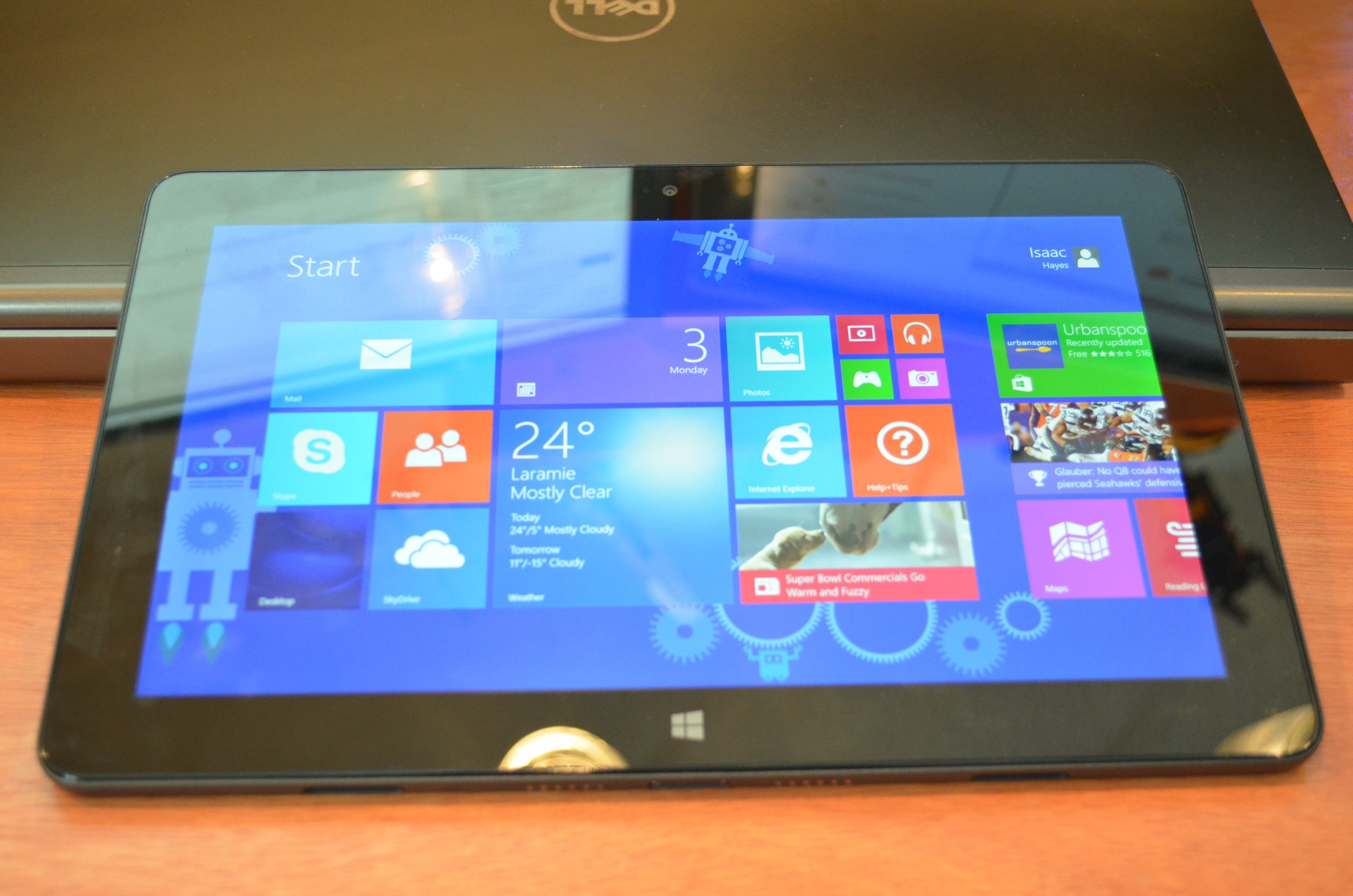
Dell Venue 11 Pro
Dell Venue 11 Pro
I bought a Dell Venue 11 Pro from the Microsoft Store while I was in Chicago for work related training. It has the Intel Atom Z3770 “Bay Trail” CPU and runs full Windows 8.1! I’m super excited about the Venue 11 due to the fact that I now have a computer I can easily get out on crowded airplanes to do programming and design work on. I love my 17 inch Dell Precision work laptop but at 8 lbs and as wide as it is it just isn’t easy to work on from an airplane seat back tray table with limited elbow room. The Venue 11 Pro should solve that problem for me and also allow me to mess with my designs while hanging out in the living room with the wife. I’m waiting for the keyboard/trackpad dock to arrive in the mail this week which should allow it to function like a standard 11″ laptop when the tablet is docked in it.
After only three days my first impressions are highly positive. Its super zippy for a mobile style processor and has run everything I’ve thrown at it so far. I have Visual Studio 2013 loaded on it along with the IDEs for Arduino and MikroC. All run like a champ. It evens runs Torchlight 2 for some real computer gaming on the go! Next step will be to load Eagle CAD and a 3D modelling package on it for 3D Printing. I’m pretty confident those will run just fine as well. It only has 64Gb of storage space which is a little restricting but should be just enough. I may need to start installing some applications on a USB 3.0 Flash Drive at some point.
My other pickup was a photography lightbox from a company called Cowboy Studio. Taking pictures on my desk don’t always turn out the best so I’m hoping this should make things a lot easier to see when trying to photograph details. The premise being it makes an “infinite white” background. As you can see I need to do some ironing of the cloth insert but I’m pretty happy with how the picture of my Arduino turned out. I don’t know that I’ll use it for everything since I don’t have a space where I can just leave it up all the time but it’s handy for pictures I just can’t get to turn out otherwise. At only $12 it was hard to turn down.
One of my current problems is how to get more people interested in microcontroller programming and robotics. Microcontrollers are cheap through the likes of the Arduino but until you attach cool things to them they are quite boring left alone. But how do you start someone going when the things you attach are complicated and often expensive… LEGOS! Few are the households that don’t have access to standard Legos. Add to that a Lego Power Functions motor and gear kit which can be had for as cheap as $10 on ebay and you’re up and running!
I’ve started a project to hack Lego motors for easy attachment to an Arduino. The benefits of this are two fold:
Ease and Low Cost of Lego robot platform building
Massive Arduino code library and documentation availability from all over the internet
My goal is to create a project anyone with Legos and an Arduino could put together to use as a robotics platform. My plan is to start with simple motor control and move on to more advance control.
Here are a few of my possible plans:
Wire project with no destruction of Lego motors or attached cables. (Hacking extension cables for Arduino connection)
Basic Motor Speed Control using Arduino and cheap motor driver from Pololu.com
Remote control over Arduino serial terminal
Remote control over WiFi using CC3000 Wifi shield for Arduino from Adafruit
PC Interface for WiFi robot control using C#
Android Interface for Wifi Robot control (possibly using Basic4Android, we’ll see)
3D Printed Lego Compatible mounting blocks for Arduino (entirely dependent on me getting a 3D Printer, hint: watch this blog)
Addition of webcam stream using Raspberry Pi or upcoming Arduino Tre
Some of these are stretch goals but you can never plan to big as long as you keep your priorities in order! So here we go! Hopefully I’ll have Part 1 up soon which deals with starting equipment and hacking the Lego Power Functions cables for connection to a motor driver.