
My first working laminar fountain
Water water everywhere! There are no two ways about it, water fountains are just plain fun. Show a water fountain to any five year old and just see if they don’t start playing and giggling. Which leads me to this conclusion: I never grew up because I still get a ridiculous grin on my face when I get to play in a water fountain. And the coolest of all the fountains in my opinion is the laminar fountain. I built a laminar fountain a few years back and am now working on designs for a 3D Printed laminar fountain which I will post online once I get a semi-working alpha version. In preparation for all that let me explain a little about what laminar flow and fountains are.
What is laminar flow?
The simplest way to explain laminar is probably to say that it is the opposite of turbulent flow. Turbulent flow is the most common type of flow you will see in nature. A drinking fountain is a good example of turbulent flow with how blobby and wiggly the water is when it comes out. White water rapids in a river would be an extreme case of turbulent flow. So in contrast, laminar flow is super smooth flowing liquid or gas. The full reality of laminar flow is that it means all of the water particles are flowing exactly parallel to each other, in the same direction, and as such are not bumping in to one another.

Laminar flow profile showing the velocity of water as it moves through a pipe. (Taken from wikipedia)
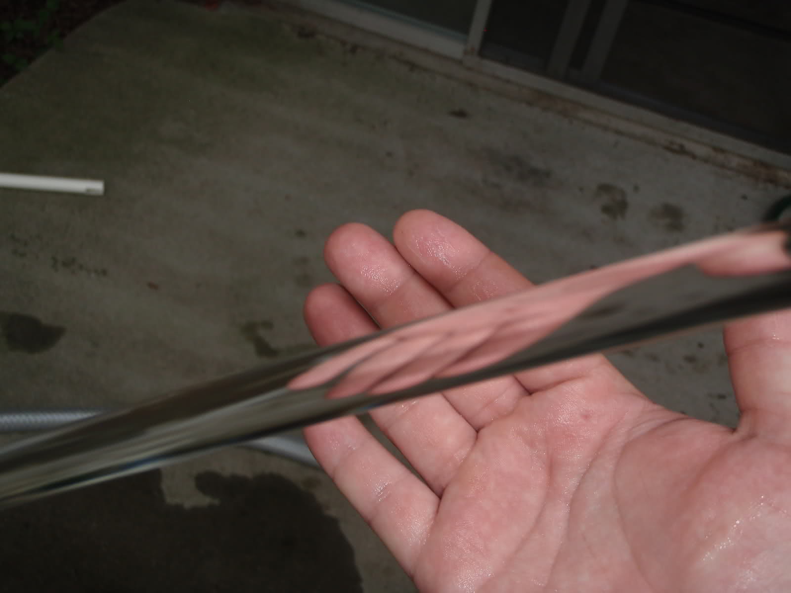
Real world picture of a laminar water stream after it exits my laminar fountain. Because the water is all flowing in the same direction it stays perfectly together and creates a glass rod effect where light can pass right through.
So why it cool?
Because it’s science! But also because it has some really cool application properties we can make use of:
1) Its moving… buts it doesn’t look like it
Because a laminar stream is perfectly smooth the flow path will stay in exactly the same place at all times. A traditional fountain will wobble and sputter as it pumps water out which makes it very obvious that the water is moving since you can follow the individual water blobs as they pass through the air. A laminar stream is perfectly uniform and does not waver which means there are now individual water droplets to follow with your eyes. The water is flowing quickly but its hard to tell. It literally looks like a perfect glass arch coming from the fountain going all the way to where it hits lands. (See the picture above)
2) No splash
Because the water stream is so smooth it will not break apart when it encounters another body of water or smooth object. If it lands in a pool of water it will disappear without a trace. If you put a smooth ball in its way it will spread out and wrap around the ball without splashing. Its a really cool effect and also has the benefit of making it quiet too!
3) It Jumps
Because the flow stream is so smooth it has a nifty visual effect when you suddenly block the stream. It looks like the stream is “jumping”. The water that is not blocked continues to fly through the air on the original path and stays together. You get little water snakes that that fly through the air. If you string multiple fountains together you can create the illusion that water is jumping from one fountain to the next.
4) It transmits light like a fiber optic cable
A fiber optic cable is a perfectly smooth medium that transmits light from one end to the other. The perfectly smooth sides of the cable reflect the light inside back in to the cable to keep it bouncing down the length until it reaches the other end. A laminar stream also has super smooth sides and therefore will also bounce light back inside of itself. This means that if you shine a bright enough light directly in to the laminar stream it will light up all the way from end to end! Even around the curve!
Here is a cool video that shows the laminar fountain forum user MagicNozzle posted of his home made fountain that demonstrates several of these properties (feel free to skip ahead, the night shots at the end are especially cool). Original forum post HERE
Laminar Maths:
If you’re in to math and the equations that govern when a stream is laminar than this is the section for you. I find it super cool how this works so lets dig in!
In an engineering fluid dynamics class (study of moving liquids, a really fun course) you learn about the Reynolds number which will tell you if a fluid’s flow is laminar, transitional, or turbulent. Here is the equation from Wikipedia:

AHHHHHH!!!1!1!! Maths! *Deep Breath* This equation is actually super simple so hold on and keep reading.
Hold on, we’ll kick that scary equation in the teeth. Lets start by focusing on the first variation of the equation listed.
Re = (p*v*D)/u
Two of those are actually constants. p is the density of water which we can google (1000Kg / m^3) and u is the dynamic viscosity of our fluid (water is 0.000404 at room temperature). So putting those back in and simplifying we get this:
Re = (2.475×10^6)*v*D
That’s not so bad. v is the velocity of our fluid in the pipe in meters per second and D is the internal diameter of our pipe in meters which should be pretty easy to calculate. Once we have our Reynold’s Number (Re) we can see if the flow will be laminar. An Re value below 2300 means that the flow is Laminar. An Re value between 2300 and 4000 is Transitional and an Re value above 4000 is Turbulent. All this means that we need to adjust our water velocity and pipe diameter to get an Re below 2300 for our fountain. That’s all the math!
How the math works in real life:
So now that we have the math (or trust me if you didn’t read it) we can interpret it. This is what it all boils down to in real life:
The faster the velocity of the fluid and the bigger the pipe, the more turbulent the flow will be.
Or inversely:
The slower the fluid and the smaller the pipe the more laminar the flow will be.
So to put this in to the real world lets tackle one problem at a time and start with velocity. We need a certain minimum amount of volume flow to achieve the fountain size we want. For instance, the pump I used in the pictures above is rated at 500 gph (gallons per hour) which gave me the nice big water arch you see. The problem shows up now in that the velocity is found by dividing the flow rate by the cross sectional area of the pipe which is a function of pipe diameter as well! So we need a bigger diameter to slow the velocity down but a smaller diameter to get a low reynolds number…… Crap.
But what if I told you we could have a separate diameter to use for velocity and the diameter in the Reynold’s equation? The trick is to take a large pipe (8 inch PVC here) and pack it full of small pipes (drinking straws). This way you get to use the large diameter of the PVC for the velocity part and the small individual diameters of the drinking straws for the Reynold’s diameter. Bingo! We can now achieve laminar flow!

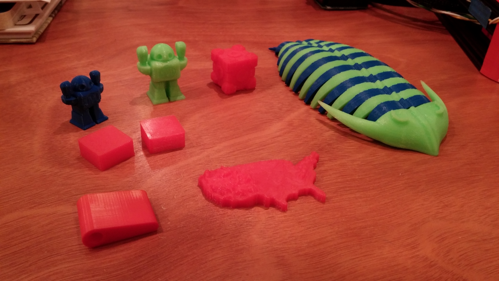
Inside my laminar fountain are nearly 2000 drinking straws to give a small diameter to the water flowing through while keep the slow velocity of a big 8 inch outer pipe.
Theory crafting complete!
That’s it for the what a laminar fountain is. Stay tuned for some more posts talking about my first laminar fountain and how I am hoping to use my 3D Printer to start a new cycle of designs!