Lego Power Functions Hacking Guide – Part 3 – Wire Hacking
Part 1 – Introduction
Part 2 – Equipment
Part 3 – Wiring Hacking
Part 4 – Wiring Arduino (coming soon)
Its time to hack! Break out the wire cutters and soldering irons cause its about to get real.
Step 1 – Grab your LEGO PF extension cables
The first thing we will need to do is prepare our extension cables so that one end can be hooked up to our legos and the other can go in to a breadboard for attachment to Arduino and motor controller.

LEGO PF Extension Wires – Top wire is hacked, bottom is a normal wire before hacking
As you can see in the picture above the extension wires have two different colored heads on them, one light grey and one dark grey. We’re going to cut off the light grey end as close as possible to the plastic head to leave as much wire as we can. (Side note: the underside of the light grey end converts PF to old Mindstorms motors which is why we are cutting off that end). The goal is to achieve what you see with the top wire in the picture. A LEGO connector on one end and bare wires on the other.
Step 2 – Cut and Strip the wires
As mentioned above, take your extension cable and cut light grey end off as close to the plastic as possible. You should come out with the four wires that make up the cable all stuck together by their insulation. Now we need to prep the wires for use with a bread board

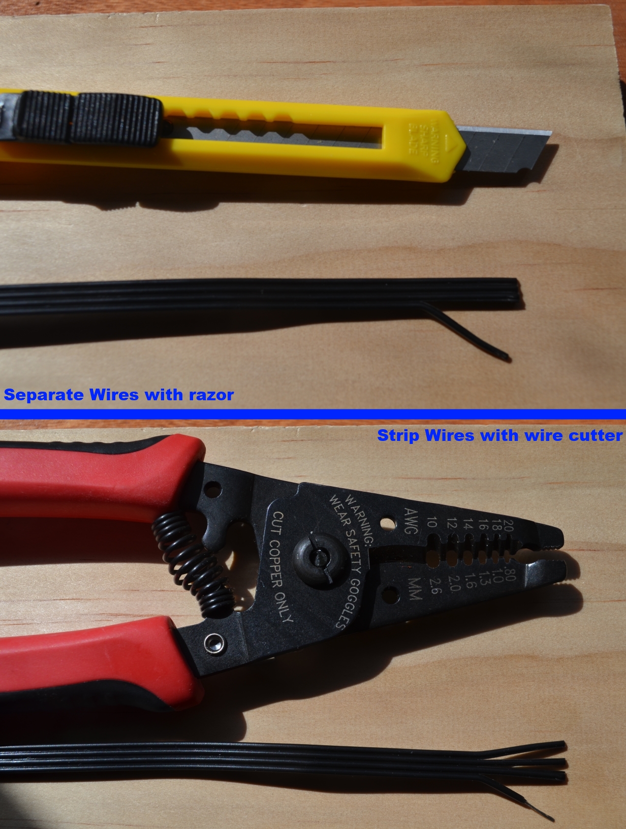
Separate then strip each wire
The first thing is to separate each of the four wires from each other using a razor or utility knife to cut the areas between each wire’s insulation. The insulation is thin so you have to be careful to stay straight and not bite in to a wire. I find this easiest by laying the blade edge flush with the area to be cut and then pushing straight down to do the cut all at once.
Next you need to strip the separated wires of their insulation. I used a wire stripper that can do 22 gauge stranded wire (20 gauge solid). I highly recommend a wire stripper as seen in the picture as the wire is very small and stranded which makes it easy to cut off strands when doing it with a razor blade.
Step 3 – Tin the wires and do it again for a second cable!
The final step is to tin the wire ends. This means to use a soldering iron to apply a small amount of solder to the end and bind the strands all together. This makes is much much easier to insert the wires in to a solder-less breadboard for use with the Arduino. You should end up with an end that looks something like the picture below. For help with Tinning do a search on youtube as there are many examples. We will need two of these cables so make sure you complete a wire in the exact same way.

Wires tinned and ready for use!
Step 4 – Know your wires!
Congratulations! You have two wires hacked and ready to go (hopefully). Now we need to learn a little something about what each of the four wires does. In the picture below I have labeled each of the four wires from the top view of the cable (Lego nubs facing up on the connector)

Power Functions cable showing the use of each wire
Power Functions Wires:
- GND – ground wire – Always connected (0V regardless of battery pack direction)
- C1 – control wire 1 – 9V when battery pack is forward, 0V when in reverse
- C2 – control wire 2 – 0V when battery pack is forward, 9V when in reverse
- 9V – power wire – On when battery pack is on (9V regardless of pack direction)
The two outside wires are our power and ground. Anytime a LEGO battery pack is connected and turned on these wires will be the same and do not change polarity. The two inside wires are the motor control wires that power the motors themselves. When a battery pack has its direction switch changed it reverses the polarity of these two. When C1 is high and C2 is low the motors rotates forwards. When C1 is low and C2 is high the motor rotates backwards. If you have a PF infrared speed controller in your system the speed controller applies a PWM signal to C1 or C2 to regulate the speed.
Step 5 – Our design
What we are going to do is use one of our cables to draw power from the LEGO battery pack via the outside two wires and then use our second cable with the inside two wires to attach the PF motor to our motor controller. Stay tuned for how to wire this up with the Arduino!
Guide Table of Contents
Part 1 – Introduction
Part 2 – Equipment
Part 3 – Wiring Hacking
Part 4 – Wiring Arduino (coming soon)